Solenoid Valve Electrical Diagram . The actuator takes the form of. the solenoid valve circuit diagram shows the electrical connections and components used to control the operation of the solenoid. the solenoid valve is the indispensable electrical circuit component in controlling fluid flow. The wiring diagram for a 24vdc solenoid. solenoid valve symbols in fluid power diagrams. the solenoid coil is used to operate the valve, by passing an electrical current through it to create an. While its functional ability to open and close pathways. this diagram helps in ensuring that the valve is wired correctly and can function properly. Fluid power drawings are crafted up by engineers to understand and analyze power units.
from mavink.com
the solenoid valve is the indispensable electrical circuit component in controlling fluid flow. The actuator takes the form of. solenoid valve symbols in fluid power diagrams. While its functional ability to open and close pathways. the solenoid valve circuit diagram shows the electrical connections and components used to control the operation of the solenoid. the solenoid coil is used to operate the valve, by passing an electrical current through it to create an. Fluid power drawings are crafted up by engineers to understand and analyze power units. The wiring diagram for a 24vdc solenoid. this diagram helps in ensuring that the valve is wired correctly and can function properly.
Electric Wiring Diagram For Solenoid Valves
Solenoid Valve Electrical Diagram the solenoid coil is used to operate the valve, by passing an electrical current through it to create an. solenoid valve symbols in fluid power diagrams. Fluid power drawings are crafted up by engineers to understand and analyze power units. the solenoid valve circuit diagram shows the electrical connections and components used to control the operation of the solenoid. the solenoid valve is the indispensable electrical circuit component in controlling fluid flow. While its functional ability to open and close pathways. this diagram helps in ensuring that the valve is wired correctly and can function properly. the solenoid coil is used to operate the valve, by passing an electrical current through it to create an. The wiring diagram for a 24vdc solenoid. The actuator takes the form of.
From proper-cooking.info
Solenoid Valve Diagram Solenoid Valve Electrical Diagram the solenoid valve circuit diagram shows the electrical connections and components used to control the operation of the solenoid. The wiring diagram for a 24vdc solenoid. the solenoid coil is used to operate the valve, by passing an electrical current through it to create an. the solenoid valve is the indispensable electrical circuit component in controlling fluid. Solenoid Valve Electrical Diagram.
From wirewiringhertzog.z19.web.core.windows.net
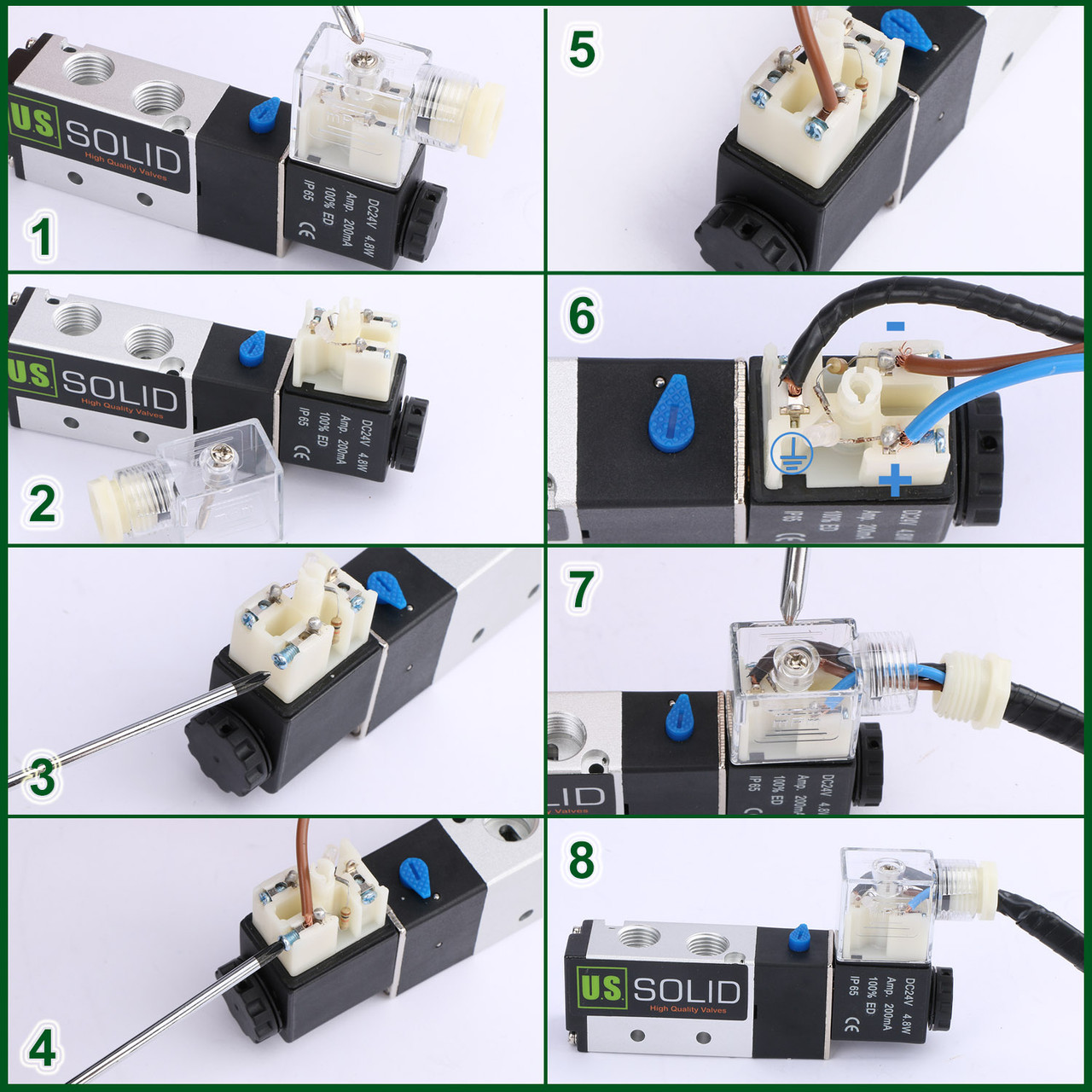
Solenoid Valve Wiring Connection Solenoid Valve Electrical Diagram the solenoid coil is used to operate the valve, by passing an electrical current through it to create an. the solenoid valve is the indispensable electrical circuit component in controlling fluid flow. While its functional ability to open and close pathways. this diagram helps in ensuring that the valve is wired correctly and can function properly. The. Solenoid Valve Electrical Diagram.
From instrumentationtools.com
What is a 4way Solenoid Valve ? Instrumentation Tools Solenoid Valve Electrical Diagram The wiring diagram for a 24vdc solenoid. the solenoid coil is used to operate the valve, by passing an electrical current through it to create an. this diagram helps in ensuring that the valve is wired correctly and can function properly. The actuator takes the form of. While its functional ability to open and close pathways. solenoid. Solenoid Valve Electrical Diagram.
From instrumentationtools.com
Four Way Solenoid Valve Working Principle InstrumentationTools Solenoid Valve Electrical Diagram The actuator takes the form of. The wiring diagram for a 24vdc solenoid. the solenoid valve is the indispensable electrical circuit component in controlling fluid flow. While its functional ability to open and close pathways. the solenoid valve circuit diagram shows the electrical connections and components used to control the operation of the solenoid. the solenoid coil. Solenoid Valve Electrical Diagram.
From decoradosdeunas.blogspot.com
View Wiring Diagram Solenoid Valve Pictures decorados de uñas Solenoid Valve Electrical Diagram The actuator takes the form of. the solenoid coil is used to operate the valve, by passing an electrical current through it to create an. solenoid valve symbols in fluid power diagrams. While its functional ability to open and close pathways. Fluid power drawings are crafted up by engineers to understand and analyze power units. the solenoid. Solenoid Valve Electrical Diagram.
From mavink.com
Electric Wiring Diagram For Solenoid Valves Solenoid Valve Electrical Diagram The wiring diagram for a 24vdc solenoid. solenoid valve symbols in fluid power diagrams. this diagram helps in ensuring that the valve is wired correctly and can function properly. Fluid power drawings are crafted up by engineers to understand and analyze power units. the solenoid coil is used to operate the valve, by passing an electrical current. Solenoid Valve Electrical Diagram.
From www.tlxtech.com
Latching Solenoid Theory TLX Technologies Solenoid Valve Electrical Diagram The wiring diagram for a 24vdc solenoid. solenoid valve symbols in fluid power diagrams. While its functional ability to open and close pathways. Fluid power drawings are crafted up by engineers to understand and analyze power units. this diagram helps in ensuring that the valve is wired correctly and can function properly. the solenoid valve circuit diagram. Solenoid Valve Electrical Diagram.
From guidedbrewsqueakings.z21.web.core.windows.net
Solenoid Schematic Diagram Solenoid Valve Electrical Diagram the solenoid valve is the indispensable electrical circuit component in controlling fluid flow. solenoid valve symbols in fluid power diagrams. the solenoid valve circuit diagram shows the electrical connections and components used to control the operation of the solenoid. The actuator takes the form of. While its functional ability to open and close pathways. the solenoid. Solenoid Valve Electrical Diagram.
From forumautomation.com
What is Solenoid valve and How it is used? Valves Industrial Solenoid Valve Electrical Diagram the solenoid valve circuit diagram shows the electrical connections and components used to control the operation of the solenoid. the solenoid coil is used to operate the valve, by passing an electrical current through it to create an. solenoid valve symbols in fluid power diagrams. this diagram helps in ensuring that the valve is wired correctly. Solenoid Valve Electrical Diagram.
From schematiclistneustadt.z19.web.core.windows.net
3 Wire Solenoid Valve Wiring Diagram Solenoid Valve Electrical Diagram this diagram helps in ensuring that the valve is wired correctly and can function properly. the solenoid valve circuit diagram shows the electrical connections and components used to control the operation of the solenoid. solenoid valve symbols in fluid power diagrams. The actuator takes the form of. The wiring diagram for a 24vdc solenoid. the solenoid. Solenoid Valve Electrical Diagram.
From mydiagram.online
[DIAGRAM] 3 Pole Solenoid Valve Wiring Diagrams Solenoid Valve Electrical Diagram solenoid valve symbols in fluid power diagrams. the solenoid valve circuit diagram shows the electrical connections and components used to control the operation of the solenoid. While its functional ability to open and close pathways. the solenoid coil is used to operate the valve, by passing an electrical current through it to create an. The wiring diagram. Solenoid Valve Electrical Diagram.
From nlo-ru.com
Wiring Diagram Solenoid Valve Electrical Diagram Worksheets Solenoid Valve Electrical Diagram While its functional ability to open and close pathways. The wiring diagram for a 24vdc solenoid. the solenoid coil is used to operate the valve, by passing an electrical current through it to create an. this diagram helps in ensuring that the valve is wired correctly and can function properly. Fluid power drawings are crafted up by engineers. Solenoid Valve Electrical Diagram.
From mydiagram.online
[DIAGRAM] 12v Solenoid Valve Wiring Diagram Schematic Solenoid Valve Electrical Diagram Fluid power drawings are crafted up by engineers to understand and analyze power units. this diagram helps in ensuring that the valve is wired correctly and can function properly. solenoid valve symbols in fluid power diagrams. the solenoid coil is used to operate the valve, by passing an electrical current through it to create an. While its. Solenoid Valve Electrical Diagram.
From circuitdataseptennium.z14.web.core.windows.net
Solenoid Valve Schematic Explained Solenoid Valve Electrical Diagram the solenoid coil is used to operate the valve, by passing an electrical current through it to create an. the solenoid valve is the indispensable electrical circuit component in controlling fluid flow. The wiring diagram for a 24vdc solenoid. this diagram helps in ensuring that the valve is wired correctly and can function properly. The actuator takes. Solenoid Valve Electrical Diagram.
From enginedbkoch.z13.web.core.windows.net
2 Way Solenoid Valve Schematic Solenoid Valve Electrical Diagram The wiring diagram for a 24vdc solenoid. the solenoid valve is the indispensable electrical circuit component in controlling fluid flow. The actuator takes the form of. Fluid power drawings are crafted up by engineers to understand and analyze power units. solenoid valve symbols in fluid power diagrams. While its functional ability to open and close pathways. the. Solenoid Valve Electrical Diagram.
From www.iqsdirectory.com
3Way Solenoid Valve What Is It? How Does It Work? Solenoid Valve Electrical Diagram the solenoid coil is used to operate the valve, by passing an electrical current through it to create an. the solenoid valve is the indispensable electrical circuit component in controlling fluid flow. Fluid power drawings are crafted up by engineers to understand and analyze power units. the solenoid valve circuit diagram shows the electrical connections and components. Solenoid Valve Electrical Diagram.
From mydiagram.online
[DIAGRAM] 12v Solenoid Valve Wiring Diagram Schematic Solenoid Valve Electrical Diagram the solenoid coil is used to operate the valve, by passing an electrical current through it to create an. this diagram helps in ensuring that the valve is wired correctly and can function properly. Fluid power drawings are crafted up by engineers to understand and analyze power units. The wiring diagram for a 24vdc solenoid. solenoid valve. Solenoid Valve Electrical Diagram.
From wireenginetracheated.z14.web.core.windows.net
Solenoid Valve Schematic Explained Solenoid Valve Electrical Diagram this diagram helps in ensuring that the valve is wired correctly and can function properly. While its functional ability to open and close pathways. solenoid valve symbols in fluid power diagrams. the solenoid coil is used to operate the valve, by passing an electrical current through it to create an. the solenoid valve circuit diagram shows. Solenoid Valve Electrical Diagram.